Evolution of a Blog

This blog has evolved as I have as a maker. It starts at the beginning of my journey where I began to re-tread my tires in the useful lore of micro electronics and the open-source software that can drive them. While building solutions around micro-electronics are still an occasional topic my more recent focus has been on the 3D Printing side of making.

Thursday, August 23, 2012

Python to Arduino Interface - Download

Download the Py2Ard Interface Library.  There are four files in this archive:
  • Py2Ard.ino - The sketch that provides the Arduino side of the interface.
  • Py2Ard.py - Python code that provides the host side of the interface - in my case running on a Raspberry Pi.
  • zzTestMotor.py - Test showing control of a motor.
  • zzTestLib.py - LED blink test also showing the use of Debug and Trace functions.
Please leave a comment below and I will let you know when a new version is available.

The above library is described in two posts, Part 1, and Part 2.


*** Note Note Note Note Note Note Note ***

I am a procedural guy trying to work in the object world and not getting far yet as you may notice from this code!   That said I am not sure WHY my call and return structure for this library is such that the call to the library returns only a status and then you have to go get the value (assuming the library returns one). 

I did not want to throw exceptions though I probably should but I am going to pivot to returning the value and then require a check for a clean return.   While I am doing this I will add an option where a bad return will throw an exception.

*** Note Note Note Note Note Note Note *** 

I have implemented this change in the new libraries available for download here and described here.

Python to Arduino Interface - Part 1

Once I started thinking about my project I realized that I was going to need to find or develop an interface library to connect the RPi running Python with the Arduino.  I found some samples on the web but not the complete library that I was looking for so decided to write my own.

I envisioned something that would be reasonably bullet proof, support the 'standard' Arduino functions while leaving room for custom expansion, use a minimum of time for communications (e.g. small command/response size), and have an optional mode of operation for debugging.

The library that I developed (Py2Ard Interface Library) is available with no express or implied warranty if you wish to experiment with it yourself.

The interface is driven from the Python side so the Arduino loop basically waits for serial input.  Handshake is initiated by a "%" to which a "#" is sent in response.  The command is then sent terminated by a "@".  Results are returned to Python with a prefix of "0" for OK or "1" for error followed a return value (0 if not appropriate) and then a narrative response (if debug is on):

    '%' -->                                from Python to Arduino
    <-- '#'                                from Arduino to Python
    'DR13@' -->                            from Python to Arduino
    <-- '0,1,Digital read from pin 13'     from Arduino to Python


Commands that provide two arguments would have a comma separating the first and second argument (e.g. DW13,20).

The standard commands implemented in the first version of this library are shown below:

    (P)in mode commands
    pinModeInput(pin)
    pinModeOutput(pin)
    (D)igital commands
    setHigh(pin)
    setLow(pin)
    digitalRead(pin)
    digitalWrite(pin, value)
 

    (A)nalog commands
    analogWrite(pin, value)
    pwmRead(pin)
    pwmPulseLow(pin, trigger)


    (S)ervo commands
    attachServo(servo, pin)
    commandServo(servo, command)
    detachServo(servo)
 

    (H)ousekeeping and debugging commands
    setDebugOn()
    setTraceOn()
    dumpTrace()
    setDebugOff()
    setTraceOff()
    setLastTime()
 

The custom commands implemented in the first version of this library are shown below (my Robot needed a compass and that requires a wire interface):

    (C)ompass commands
    compassInit()
    compassBearing()


A sample of how this library is used will be in the next post on this topic.   Part 2 of this post covers more about the library.

Monday, August 20, 2012

The Brain - Raspberry Pi - Before Receipt


Even before the RPi was delivered I was getting ready for it!   I downloaded the image for Wheezy which is an optimized version of Debian built for the Raspberry Pi.   This comes down as a disk image so I needed to find a way to get it onto an SD card since that is what the RPi boots and runs from.   I struggled a little trying to get this done on my iMac, which is my primary workstation, but decided to use Win32 Disk Manager on my Windows Laptop.

More importantly I decided to build a Python development environment on Linux running on my laptop as I could get started with some of the software that I will need ahead of having an RPi.   I decided on Ubuntu as it is based on Debian and I figured would be close enough.

The install process was simple, as easy as doing a Windows install, and the end result was pretty impressive.   Being your typical ex-corporate IT executive I had never really considered Linux but I can now see the allure.   For the grand cost of nothing I had an operating system, a development environment (choice of many), productivity software, and access to a nice little store to get more free stuff.

It also came loaded with Python so I could get started with learning both it, and more about Linux, as this is all part of me going back to my roots.

Thursday, August 16, 2012

The Platform - Rover 5

I found the Rover 5 as an economical platform to carry my chosen collection of electronics.  It can support two or four motors (not sure why you would need four), has two encoders for speed and distance measurement, and comes with a battery pack for six AA batteries.   As I unpacked it I found it to be a pretty sturdy little piece of kit. 


It is designed to be integrated with the Explorer PCB but someone handier than I could easily build their own motor controller and other kit on top of the basic chassis.
 

Wednesday, August 15, 2012

Nervous System - Explorer PCB

The Explorer PCB is designed to be integrated with the Rover 5 and provides an easy answer for integrating the Arduino with propulsion and various sensors.   It integrates with the Rover chassis for power, control of the motors, and for sensing both current draw and the rotary encoders.

It also provides power (3.3v and 5v) and control interfaces for all the servos and sensors that I will need.  It also has a battery charger built in to keep the on-board batteries up to power.  It has four IR proximity detectors on each corner of the board and is designed to support a pan and tilt sensor platform on the bow.   There is also an area for prototyping which I am not sure how or if I will use at this point.

You could accomplish all of this with individual shields but this was an easy decision for me.

Saturday, August 11, 2012

Nervous System - Arduino

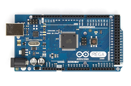
The Arduino is an open-source electronics prototyping platform with a pretty large ecosystem of add ons.   The Arduino Environment runs on your PC and allows for the writing of code in a "C" like language that can then be downloaded to the Arduino to drive a multitude of connected devices.   The environment is written in Java which obviously makes it very portable between environments if a little pokey at times.

There are a wide variety of boards but I went with the Mega as I was not sure how many interfaces that I would ultimately need.   Besides, boys with their toys always favor a name like "Mega".
Having received the board I promptly connected it to my PC, downloaded the development environment, and made the on-board LED blink.  If nothing else I had the environment setup on my Ubuntu laptop and knew that the Arduino was alive.

/*
  Blink
  Turns on an LED on for one second, then off for one second, repeatedly.
  This example code is in the public domain.
 */

// Pin 13 has an LED connected on most Arduino boards.

// give it a name:
int led = 13;

// the setup routine runs once when you press reset:
void setup() {               
  // initialize the digital pin as an output.
  pinMode(led, OUTPUT);    
}

// the loop routine runs over and over again forever:
void loop() {
  digitalWrite(led, HIGH);   // turn the LED on (HIGH is the voltage level)
  delay(1000);               // wait for a second
  digitalWrite(led, LOW);    // turn the LED off by making the voltage LOW
  delay(1000);               // wait for a second
}


I actually didn't even write anything as the above is one of the many samples that comes with the Arduino environment!


Overview of the Major Parts

With the brain in hand (ok, not exactly in hand since it is on a multi-month back order) we could still get the parts and configure my laptop as a linux machine to get started on the development.    So here is what we are going to use as our robot platform:

The Brain:   We already know that the Raspberry Pi is going to be the brain but we need a mission for the robot.   I am not looking to do rocket science so my mission is reasonably simple.   In the first state I just want to be able to control the robot via a web interface.   Clumsy but it will get things working.  Then in an autonomous mode I would like the robot to be able to map a room.

The Platform: The Rover 5 was my choice of a platform.  A treaded two or four motor system with encoders for distance measurement.  A simple platform for the rest of my stuff!

Platform - Rover 5

The Nervous System:   While the Raspberry Pi features a pretty good low level peripheral interface I needed more so enter an Arduino Mega.   This provides the spinal cord and then enter an Explorer PCB for the rest of the nervous system.

Nervous System - Arduino
Nervous System - Explorer PCB

Sensory System:  The Explorer PCB provides current sensing, encoders, and four corner proximity sensors.   To this I am going to add an ultrasonic range finder on a pan/tilt mount and a compass for direction finding.   Finally, a webcam on the pan/tilt mount will connect directly to the RPI.
Almost all of the bits-and-bobs that I show and talk about on this Blog were purchased from the RoboSavvy UK Store.   They have good prices, fast dispatch, and good customer service the one time I needed it.


Tuesday, August 7, 2012

The Idea

When I heard about the Raspberry PI I knew that I had to have one.

Rasberry Pi

I had no idea what for....but I know I needed one badly!    My CS education featured a lot of work on early Unix machines and the fridge size boxes we used were probably less powerful than the credit card sized RPI.   I was also an early adopter of a variety of personal computers including an Altair, a Radio Shack TRS-80, a variety of z80 and 8080 based machines, and the list goes on from the antiques to my current iMac 27.

So, I had to have one.  What to do with it?   I already have the iMac, a Mac Mini, a laptop, a iPad, an Android Pad, and an iPhone so I am not short of electronics.   I also have several media players so gen'ing up the RPI as a media player didn't sound exciting.

Then the Mars Rover landed and I had my idea!   I have always been interested in the interface between a computer and physical devices so this was interesting.   In addition I could do the development in Python learning another language on my route back to my past.